IV Site Detection System: Automated Vein Recognition for Safer IV Insertion
Project Goal: To design and build an end-to-end computer vision system that detects optimal IV insertion sites on the forearm, communicates coordinates to an ESP32-controlled laser pointer, and verifies accuracy through a pixel-to-millimetre calibration workflow.
Tech Stack: Python, FastAPI, React, OpenCV, TensorFlow
Project Overview
Intravenous (IV) insertion is one of the most common clinical procedures, yet it remains highly dependent on practitioner experience. Failed attempts lead to patient discomfort, bruising, and clinical inefficiency. This project aimed to reduce that variability by building an automated system that identifies optimal insertion sites and provides physical guidance via laser marking.
The system operates across three distinct layers:
- Machine Learning Pipeline: A Python-based engine that handles vein segmentation, feature extraction, and Gradient Boosting classification to rank insertion sites.
- FastAPI Backend: A robust REST API that wraps the ML pipeline and manages low-latency communication with the microcontroller.
- React Frontend: A clinician-facing interface for image uploads, real-time annotated overlays, and triggering the physical marking workflow.
As the lead for the front-end, back-end, and machine learning stacks, I owned the end-to-end digital pipeline: from the initial pixel processing and model architecture to the development of the API and the user interface. While the project included a physical prototype and firmware for laser marking, those components were managed separately and ultimately highlighted the significant challenges of hardware-software integration.
Design Process:
Phone camera vs normal camera
After identifying the problem and our solution, we needed to decide between two alternative designs. Although we were already using hardware to project the laser onto the arm, the method of image acquisition was still up in the air. Alternative 1 was to use a mobile phone camera to take a picture of the user's arm. Alternative 2 was to order a camera and interface the firmware with it, sending the image to the server using the ESP32.
When doing a simple comparison of the two, you get the following table:
| Alternative 1 | Alternative 2 | |
|---|---|---|
| Cost | Better | Worse |
| Photo Quality | Better | Worse |
| Reproducibility | Worse | Better |
Alternative 1 was chosen.
System diagram
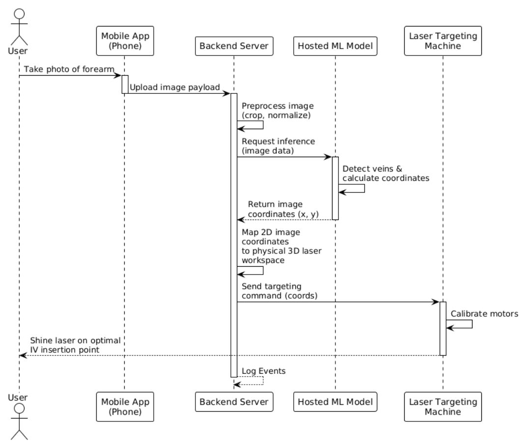
Machine learning architecture
Before I get into any iterations, I want to explain the general image workflow when something is uploaded to the system using layman's terms.
Step 1 - Figure out what kind of image it is:
Is this a near-infrared (NIR) or a regular visible light image? This is done by checking if the image is in greyscale.
Step 2 - Enhance the image:
The image must get cleaned before any detection happens. If this is an NIR image, the system applies CLAHE (a contrast enhancement algorithm) and then a bilateral filter to smooth out noise. If this is a normal image, the system finds the best colour channel and masks anything that doesn’t look like skin tone. Then CLAHE is applied twice before the brightness is normalized to deal with uneven lighting.
Step 3 - Find the Safe Zone:
Before the veins are found, the system draws an acceptance boundary where veins are treated as valid. This is a fix of two big false positives that are discussed below.
Step 4 - Locate the veins
Two different methods are used to locate veins. Adaptive thresholding inverts the image and finds regions darker than the local surroundings. Frangi vesselness filters find tubular-like structures (cylindrical and elongated). Together, noise gets removed before any candidate sites smaller than 50 pixels are discarded. Finally, locations are checked to ensure everything falls inside the safe zone previously mentioned. After this vein has been located, it is reduced to a single-pixel-wide centreline.
Step 5 - Extract Features for the model
The system samples points along every 5 pixels of every skeleton. For each point, it calculates 13 measurements (Diameter, straightness, curvature, junction distance, Y/X position, contrast, segment length, density, depth proxy, frangi response, orientation, diameter uniformity)
Step 6 - Score every point.
A gradient boosting classifier is used give each candidate a score between 0 and 1 to represent how good of an IV insertion point it would be.
Step 7 - Select the best sites
If the system just selected the best points, they would all be right next to each other. Instead, a non-maximum suppression is applied where any candidate within 20 pixels of a higher-scoring candidate gets discarded. After this, the top 5 are selected by score.
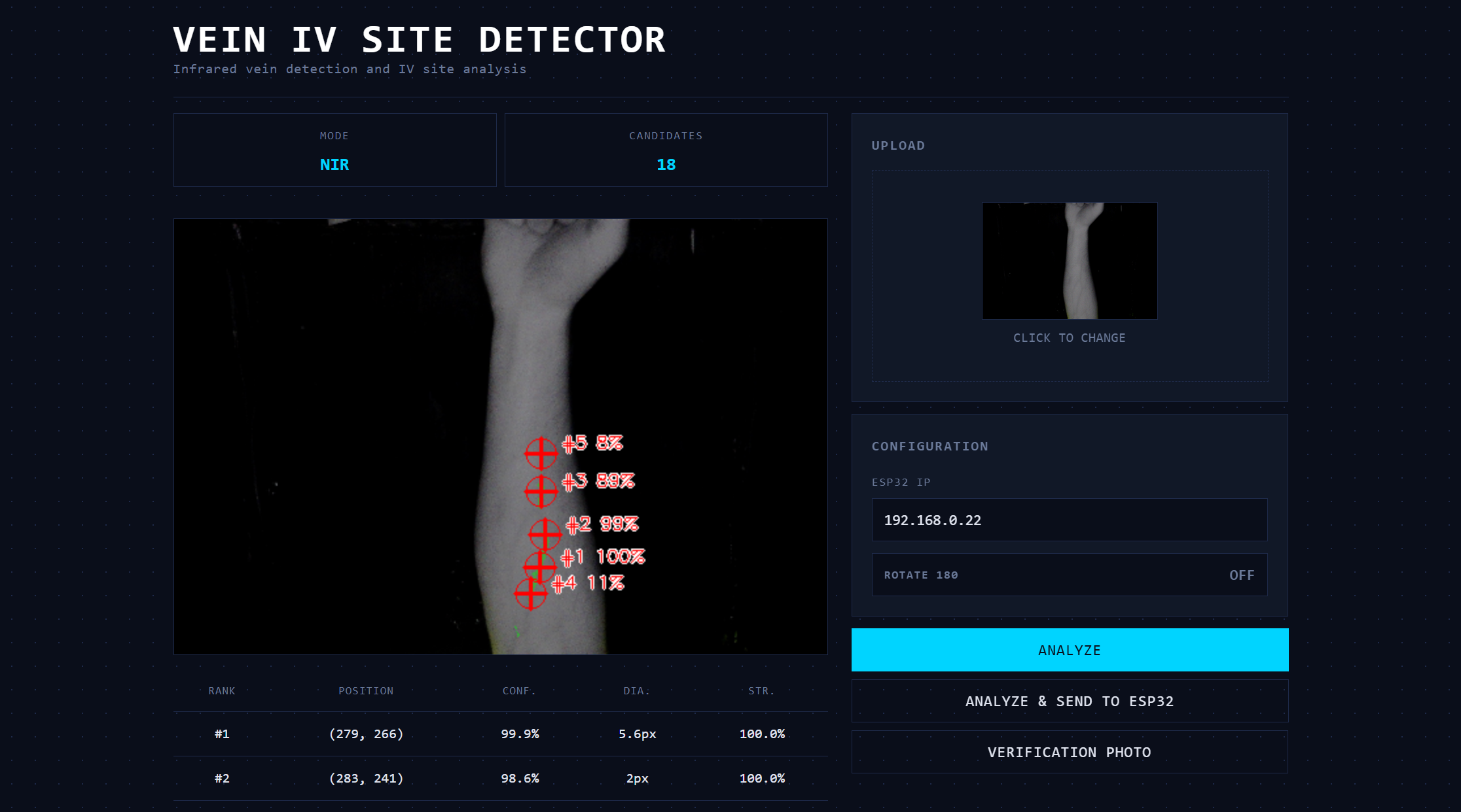
Step 8 - Render the output
A green semi-transparent overlay highlights detected vein regions. Red crosshairs levelled with its rank and confidence score are placed at each of the top 5 sites.
Continued iterations:
After the base model architecture was laid out, qualitative visual testing was conducted to spot any major bugs. Two major changes needed to be made to the model
Problem 1: The program kept segmenting the edge of the arm as a vein due to its stark contrast and straightness of the line between the arm and the background.
To fix this, more preprocessing had to be done before candidate site comparisons:
First, establish a “safe zone” inside the arm. The code found the outline of the arm, then moved its boundaries ~6% of the image size to create a smaller inner region. By essentially shrinking the area the model is allowed to look at, anything that would be an edge gets ignored entirely.
Second, score the boundary candidates lower. If a vein is located near the edge of this safe zone, it’s penalized during the relative ranking process. This means that even if false positive edge detection occurs, it won’t get picked as the best insertion site, and presumably not within the top five displayed and sent to the firmware.
Problem 2: The model was identifying creases in the hand or wrist as veins.
It's important to note that even if actual veins were found in this region, they would not be optimal IV insertion points. Inserting an IV into the palm of a hand would render that hand unmovable at the risk of the needle falling out.
To fix this, two more steps were implemented.
First, the top 20% of the image was hard blocked. Similar to how we established a better “safe zone” in the last fix, a simple one was done here to block off the hand and wrist.
Second, the vertical scoring curve was refactored. As a consequence of the first step, using the smooth bell curve previously used would be inaccurate, and areas near the top need to be nullified. As a result, the new curve was deliberately asymmetric:
| Zone (from top) | Relative Scoring Weight |
|---|---|
| Top 20% | 0 |
| 20%-60% | Score ramps linearly as you progress into the forearm |
| 60%-85% | Score stays at maximum (ideal zone) |
| Greater than 85% | Score gently drops. |
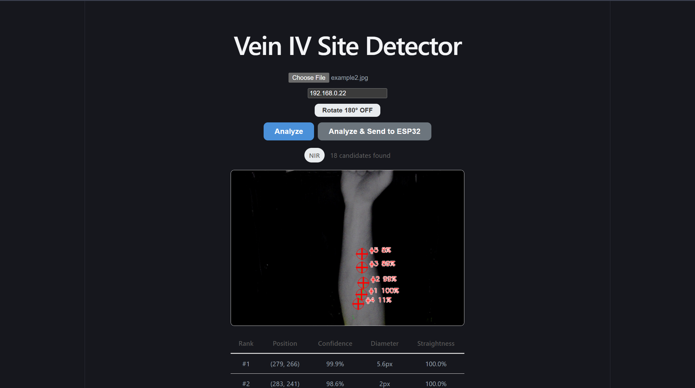
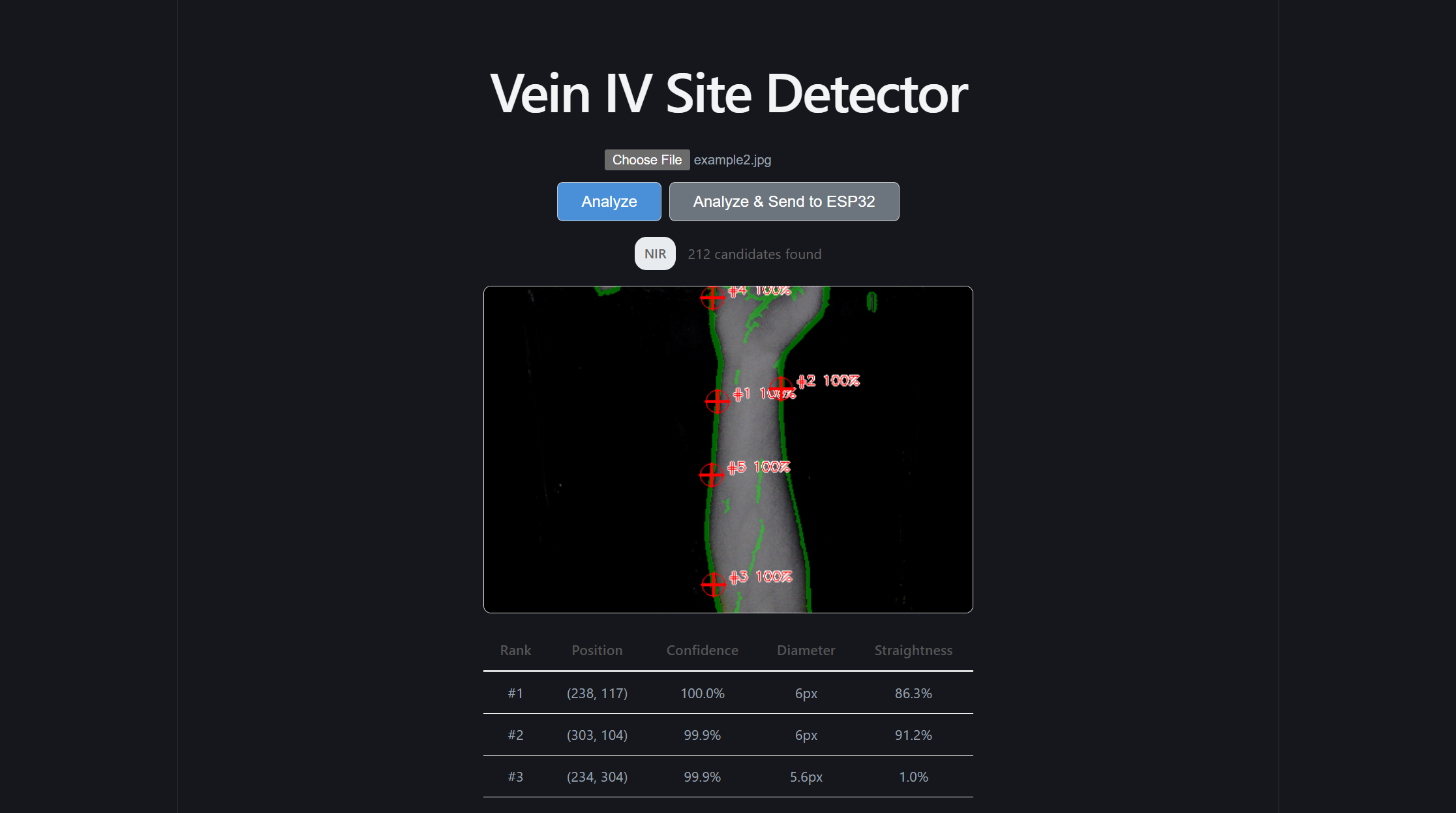
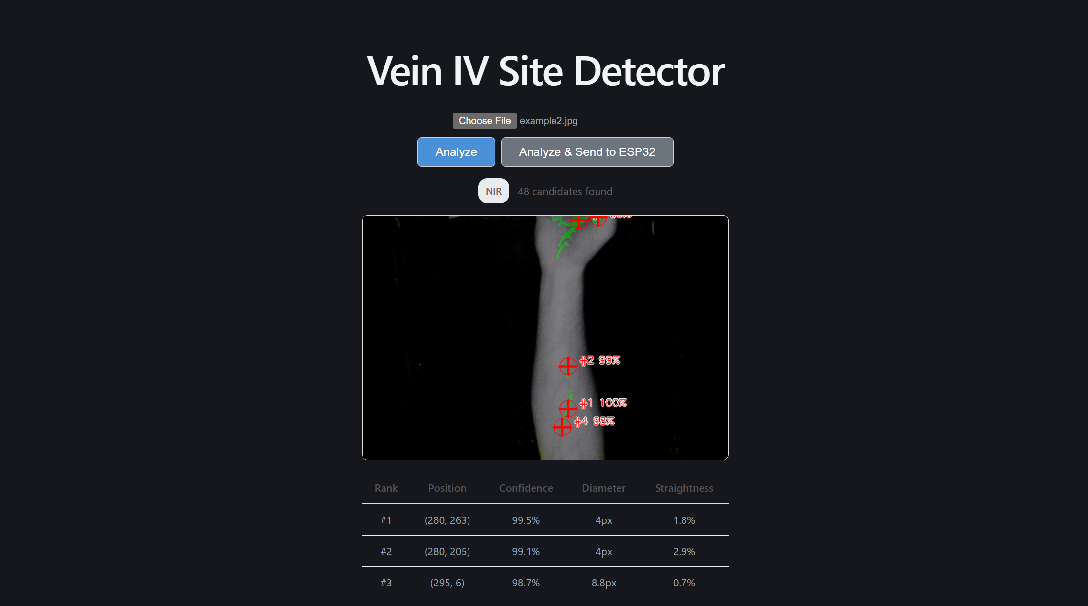
Front-end redesign
After I was satisfied with the results of the machine learning model, and I constructed the simple endpoints to reach it and send information to the ESP32, it was finally time to give the front end a refactor. At the time, it was using the default Vite styles, but I felt this site deserved a more scientific and professional look to wrap this model. I believe the differences in the site speak for themselves
Additionally, rather than set a manual timer for our inference speed test, I created the /demo subpage. This subpage accepts ten photos and automates our speed test for us!
Conclusion
Although the firmware and physical prototype did not end up being built properly, and the calibration settings weren’t set up, I still believe this product has value, and our machine learning model, front end design, and back end architecture make this product a net success!
Reflection:
Strategic Architectural Scaffolding:
I learned that senior-level engineering is about creating clear boundaries between high-reliability software and unpredictable external dependencies. By placing the ML and image processing logic behind a clean FastAPI REST boundary, I protected the core intelligence of the system from the instabilities of the firmware and physical prototype. This decoupling allowed the software stack to maintain high performance and testability even when the hardware components struggled. This makes me question how we could have further encapsulated the firmware and physical prototype. Would that have made the physical development faster?
Defensive Full-Stack Engineering:
Managing the front-end, back-end, and ML segments taught me that a system is only as strong as its weakest integration point. I shifted my focus toward building defensive data pipelines that could handle inconsistent inputs. This included implementing aggressive preprocessing for visible-light images and building a confidence-warning system in the React UI to alert clinicians when the image quality was insufficient for a reliable prediction.
The Reality of Hardware-Software Friction:
A profound takeaway from this project was the "garbage in, garbage out" principle regarding physical sensors and actuators. While the software reached a high level of mathematical precision, the physical prototype and firmware limitations introduced errors that the software could not entirely compensate for. I wonder if we could have accounted for these "physical-layer" failures in a better way? Maybe by building in calibration routines and error-logging systems that expose exactly where the precision is lost, we would have been able to more properly diagnose the problem.
Decoupling for Portability:
By extracting our signal processing and feature extraction into pure, framework-agnostic Python functions, I ensured the ML core was not held hostage by the specific web or hardware environment. This separation allowed us to run fast, reliable unit tests on the math itself, which was essential for debugging the complex coordinate transformations required for the laser marking.